ASME B18.2.6:2019 pdf free downloadFasteners for Use in Structural Applications
1 INTRODUCTORY NOTES1.1 Scope
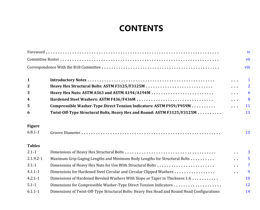
1.1.1This Standard covers the complete general and dimensional data for five products in the inch series recognized asan American National Standard. These five structural products include
(a) heavy hex structural bolts: ASTM F3125/F3125M
(b) heavy hex nuts: ASTM A563 and ASTM A194/A194M
(c) hardened steel washers — circular, circular clipped, and beveled:ASTM F436/F436M(d) compressible washer-type direct tension indicators: ASTM F959/F959M
(e) twist-off-type structural bolts — heavy hex and round:ASTM F3125/F3125M
1.1.2The inclusion of dimensional data in this Standard is not intended to imply that all products described herein arestock production sizes.Consumers should consult with suppliers concerning lists of available stock production sizes.
1.2 Dimensions
All dimensions in this Standard are in inches,unless stated otherwise, and apply to an unplated or uncoated product.When plating or coating is specified, the finished product dimensions shall be as agreed upon between supplier andpurchaser. Symbols specifying geometric characteristics are in accord with ASME Y14.5.
1.3 Options
Options, where specified, shall be at the discretion of the supplier, unless otherwise agreed upon by the purchaser with themanufacturer or distributor.
1.4 Terminology
For definitions of terms relating to fastener dimensional or component features used in this Standard, refer to ASMEB18.12.
1.5 Referenced Standards
Unless otherwise specified, the referenced Standard shall be the most recent issue at the time of order placement.Thefollowing is a list of publications referenced in this Standard:
ASME B1.1,Unified Inch Screw Threads (UN and UNR Thread Form)ASME B1.2,Gages and Gaging for Unified Inch Screw Threads
ASME B1.3, Screw Thread Gaging Systems for Dimensional Acceptability —-Inch and Metric crew Threads (UN,UNR, UN.M, and MJ)
ASME B18.2.1, Square, Hex, Heavy Hex, and Askew Head Bolts and Hex, Heavy Hex, HexFlange, Lobed Hlead, and LlagScrews (lnch Series)
ASME B18.2.2,Nuts for General Applications:Machine Screw Nuts, Hex, Square, Hex Flange, and Coupling Nuts (InchSeries)
ASME B18.2.9,Straightness Gage and Gaging for Bolts and ScrewsASME B18.12,Glossary of Terms for Mechanical Fasteners
ASME B18.18,Quality Assurance for Fasteners
ASME B18.24, Part ldentifying Number (PlN) Code System Standard for B18Fastener ProductsASME Y14.5, Dimensioning and Tolerancing
Publisher: The American Society of Mechanical Engineers (ASME),Two Park Avenue,New York,NY10016-5990(www.asme.org)
ASTM A194/A194M, Carbon Steel, Alloy Steel, and Stainless Steel Nuts for Bolts for High Pressure or High TemperatureService, or Both
ASTM A563,Carbon and Alloy Steel Nuts
ASTM B695, Coatings of Zinc Mechanically Deposited on Iron and Steel
ASTM F436/F436M, Hardened Steel Washers, Inch and Metric Dimensions
ASTM F788, Surface Discontinuities of Bolts, Screws, and Studs, Inch and Metric Series
ASTM F812, Surface Discontinuities of Nuts, Inch and Metric Series
ASTM F959/F959M, Compressible-Washer-Type Direct Tension Indicators for Use With Structural Fasteners, Inch and Metric Series
ASTM F2329/F2329M, Zinc Coating, Hot-Dip, Requirements for Application to Carbon and Alloy Steel Bolts, Screws, Washers, Nuts, and Special Threaded Fasteners
ASTM F3125/F3125M, High Strength Structural Bolts, Steel and Alloy Steel, Heat Treated, 120 ksi (830 MPa) and 150 ksi (1040 MPa) Minimum Tensile Strength, Inch and Metric Dimensions
Publisher: American Society for Testing and Materials (ASTM International), 100 Barr Harbor Drive, P.O. Box C700, West Conshohocken, PA 19428-2959 (www.astm.org)
2 HEAVY HEX STRUCTURAL BOLTS: ASTM F3125/F3125M
2.1 Heavy Hex Structural Bolt Dimensions
Bolts shall conform to the dimensions given in Table 2.1-1. Formulas for heavy hex structural bolts are given in Nonmandatory Appendix A of ASME B18.2.1.
2.1.1 Top of Head. Top of head shall be full form and chamfered or rounded with the diameter of chamfer circle, or start of rounding being equal to the maximum width across flats within a tolerance of −15% of the maximum across flats dimension. The shape of the top of the head may be flat, concave, or convex at the manufacturer’s option. If the shape is concave or convex, head height as described in para. 2.1.4 shall remain within specified limits at lowest or highest points, respectively.
ASME B18.2.6:2019 pdf free download
