ASME B16.4:2011 pdf free download Gray Iron Threaded Fittings Classes 125 and 250
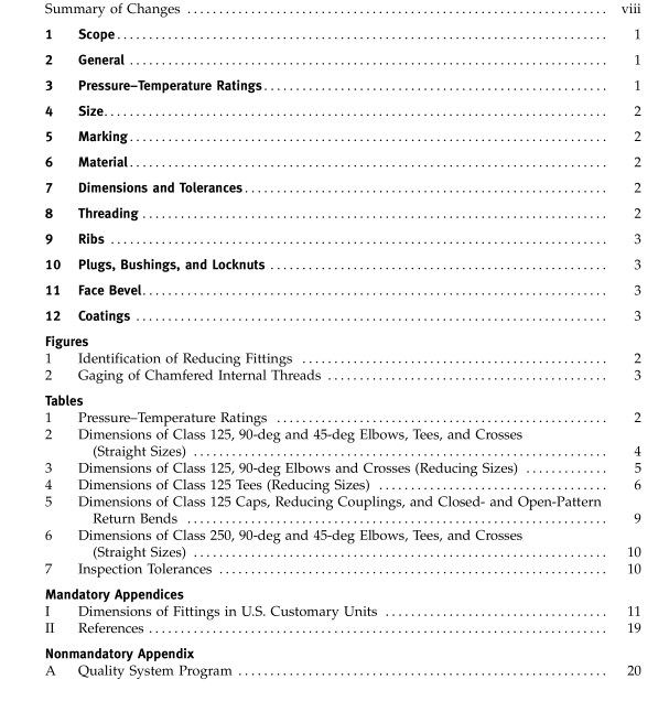
1 scoPE1.1 General
This Standard for gray iron threaded fittings.Classes125 and 250,covers:
a)pressure-temperature ratings,
(b) size and method of designating openings of reduc-ing fittings,
(c) marking,id)material.
e) dimensions and tolerances,threading, and
(g)coatings.
1.2 References
Standards and specifications adopted by reference inthis Standard are shown in Mandatory Annex I.
1.3 Quality Systems
Requirements relating to the product manufacturers”Quality System Programs are described in Nonmanda-tory Annex A.
2 PRESSURE-TEMPERATURE RATINGs
(ay Pressure-temperature ratings for these fittings areshown in Table 1.
b) All ratings are independent of the containedfluid and are the maximum nonshock pressures at thetabulated temperatures. Intermediate ratings may beobtained by linear interpolation between the tempera-tures shown.
ic)The nemperatures shown for the correspondingpressure rating shall be the material temperature of thepressure-retaining structure. Ilt may be assumed that thematerial temperature is the same as the fluid temperature.Use of a pressure rating at a malerial temperature otherthan that of the contained fluid is the responsibilityof the user and subject to the requirements of anyapplicable code.
3 sIZE
a)The sizes of the fittings scheduled in Tables 3through 7 are identified by the corresponding nominal’pipe size (NPS).
(b)For reducing tees and crosses,the size of thelargest run opening shall be given first,followed bythe size of the opening at the opposite end of the run.Where the fitting is a tee. the size of the outlet isgiven last.Where the fitting is a cross, the largest side-outlet opening is the third dimension given,followedby the opposite opening. The straight-line sketches ofFig. 1 illustrate how the reducing fittings are read.
4.MARKING
a)Each Class 125 fitting shall be marked for identi-fication with the manufacturer’s name or trademark.(b) Each Class 250 fitting shall be marked for identi-fication with:
1) the manufacturer’s name or trademark,and(2) the numerals “250.””
5 MATERIAL
Castings shall be produced to meet the requirementsof ASTMA 126,Specification for Gray lron Castingsfor Valves,Flanges, and Pipe Fittings,Class A. B orC. The manufacturer shall be prepared to certify thatthe product has been so produced and that the chemicaland physical properties thereof,as proved by test speci-mens.are equal to these requirements.
6 DIMENSIONs AND TOLERANCES
(a)Tables of center-to-end dimensions are given forstandard straight and reducing fittings. The sketches offittings shown in the Standard are representative andfor the purpose of illustration.
(by The dimensions in Tables 3 through 7 of reducing fittings are for use only when making patterns for thespecific reducing fitting in question and do not applywhen a larger size patterm is bushed to make thereducing fitting wanted.
(c) lt is recognized that some variations are abso-lutely unavoidable in the making of patterns and cast-ings. The following tolerances shall be permitted.(l ) Metal Thickness Tolerances. Metal thicknessat no point in the castings shall be less than 90% ofthe value given in Tables 3 through 7.
(2)Center-to-End Tolerances. Permitted toleranceson the center-to-end dimensions of the fittings areshown in Table 2.Tolerances for end-to-end dimcnsionsand lengths of couplings and reducers shall be twicethose given. The largest opening in a reducing fittinggoverns the tolerances to be applied to all openings.These tolerances do not apply to return bends and caps.
7THREADING
a)All fittings shall be threaded according to ASMEB1.20.1,Pipe Threads,General Purpose (Inch), and thevariations in threading shall be limited to one turnlarge or one turn small from the gaging notch on theplug when using working gages.
(b)The reference point for gaging internal fittingsthreads depends upon the chamfer diameter. When theinternal chamfer diameter exceeds the major diameterof the internal thread,the reference point is the lastthread scratch on the chamfer cone. When the internalchamfer diameter does not exceed the major diameterof the internal thread,the reference point is the endof the fitting (see Fig. 2).
ASME B16.4:2011 pdf free download
