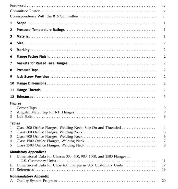
ASME B16.36:2006 pdf free download Orifice Flanges
3.3 Plugs
Pressure retaining plugs shall conform toASME B16.11,unless otherwise agreed between pur-chaser and manufacturer. Plug material shall be at leastas corrosion resistant as the corresponding flangematerial.
4SIZE
Orifice flange sizes are indicated by the nominal pipesize to which they are attached.Only those listed inTables 1 through 5; Tables 1-1 through 1-5,andMandatory Appendix l are considered standard.
5 MARKING
Flanges shall be marked as required in ASME B16.5.For welding neck flanges only, the bore diameter shallbe marked.
6FLANGE FACING FINISH
The finish of contact faces shall conform to the require-ments of ASME B16.5.
7 GASKETS FOR RAISED FACE FLANGES7.1 Gasket Thickness
Flange dimensions are based on the use of 1.5 mm(0.06 in.) thick gaskets.
7.2 Flange Gaskets Requiring Dimensional ChangesWhen the location of the pressure tap with respect tothe orifice plate is critical to the service and meteringconditions, its location may be altered to accommodateother than 1.5 mm (0.06 in.) thick gaskets or ring typejoint gaskets whose thickness may vary from that listedin in Tables 2,3,4, and 5 or those listed in Tables 1-2,I-3,1-4, and 1-5 or Mandatory Appendix Il.
The alteration of location may also be accomplishedby the removal of 2 mm (0.06 in.) from the raised faceof the flange. If an original 2 mm (0.06 in.) high raisedface is removed, the user is cautioned to limit the outsidediameter of the gasket or orifice plate to the tabulatedR dimension.
PRESSURE TAPS8.1 General
Each orifice flange shall be provided with two pres-sure tap holes extending radially from the outside diam-eter of the flange to the inside diameter of the flange.Corner taps may be used on NPS 11/2and smaller ifspace permits. See Fig.1.
For ring joint flanges listed in Tables 2 through 5,Tables I-i through I-5, and Mandatory Appendix H where radial taps will interfere with the ring groove,angular meter taps,as illustrated in Fig. 2,will berequired. Each pressure tap hole shall be equipped witha pipe plug.
8.2 Location
8.2.1 Measurement. The 24 mm (0.94 in.) dimensionfor raised face and 19 mm (0.75 in.) for ring joint shallbe measured at the bore.
8.2.2 ldentification. For ring joint flanges requiringalteration of pressure tap location due to interferencewith the ring groove other than methods provided inthis Standard, such alteration shall be identified peragreement between purchaser and manufacturer.
8.3 Pipe Connection
Unless otherwise specified, pressure tap holes may beeither tapped 5 NPT in accordance with ASME B1.20.1or 1/2 NPS socket connection in accordance withASME B16.11.
JACK SCREW PROVISION9.1 Location
Each flange shall have a machine bolt mounted in ahole drilled on the flange bolt circle center line at 90 degfrom the pressure taps, for use as a jack screw. Machinebolt shall be regular with one heavy hex nut.See Fig. 3.9.2 Slot for Nut
A slot shall be provided in the flange 2 mm (0.06 in.)wider than the width across flats of the nut. The depth ofthe slot shall admit the nut so that there is no interferencewith the joining of the flanges when bolted togetherwithout orifice plate.
9.3 Tapped Hole
As an alternative to para. 9.2,a tapped hole maybe provided and the hex nut omitted when agreed onbetween the purchaser and the manufacturer.
10FLANGE DIMENSIONs
Dimensions are listed in Tables 1,2,3,4,and 5, formetric,and Tables I-1,I-2,I-3,1-4,and 1-5,andMandatory Appendix ll for U.s.Customary.
11 FLANGE THREADS
Threaded flanges shall have an American NationalStandard taperpipe threadconforming toASME B1.20.1.
(a)The thread shall be concentric with the axis of theflange. Variations in alignment shall not exceed 5 mm/M(0.06 in./ ft).
ASME B16.36:2006 pdf free download
