ASME B16.20:2007 pdf free download Metallic Gaskets for Pipe Flanges Ring-Joint, Spiral-Wound, and Jacketed
2.7 Identification Number Dimensional reference identification riunibers are as- signed to ring-joint gaskets and are shown in Tables 3 through 8. 3 SPIRAL-WOUND GASKETS 3.1 Size and Class Spiral-wound gaskets, including centering ring and inner ring (paras. 3.2.4 and 3. 25). are identified by flange size (NPS), pressure class. and the appropriate flange standard (ASME €3165 or ASME B16.47).
3.2 Dimensions and Tolerances
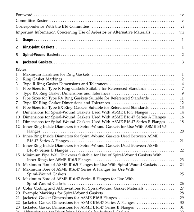
3.2.1 General. Dimensions and tolerances for spi- ral-wound gaskets, centering rings, arid inner rings shall be in accordance with Tables 9 thr-ough I I and as specitied in this section.
3.2.2 Construction. Spiral-wound gaskets shall be constructed as alternate plies (circular layers counted as revolutions) of preformed metal windings and plaint fillers that are spirally wound. For the finished gasket, the tiller shall be essentially flush with. but not below, the metal winding on both contact faces of the gasket. The metal strip in the winding shall be 0.006 in. to 0.009 in. thick. The filler matei-ia1 thickness shall be determined by the manufacturer.
3.2.3 Metal Joining. The inner windings shall have a minimum of three plies of preformed metal strip without filler. The initial two plies shall be spot- welded circumferentially with a minimum of three welds spaced at a maxiinuni distance of 3 in. The METALLIC GASKETS FOR PIPE FLANGES outer windings. which shall have a minimum of three plies of preformed metal without filler, shall bc spotwelded circumferentially with a minimum of three welds, the last of which shall be the terminal weid. The distarice of the first weld from the terminal weld shall be no greater than 1.5 in. Up to four additional loose preformed metal windings beyond the terminal weld may be used to retain the gasket into the center- ing ring.
3.2.4 Centering Ring. All spiral-wound gaskets shall be furnished assembled into a centering ring. The centering ring thickness chal1 be from 0.1 17 in. to 0.131 in. and suitably grooved on the inside diameter so as to retain thc gasket.
3.2.5 Inner Ring. Inner rings shall be furniched (a) with all spiral-wound gaskets having PTFE (polytetra- fluoroethylcne) filler material. It is recommended that inner rings be specified by the user for flexible graphite and other filler materials (if appropriate for flanges and bore sizes used), particularly wJhere experience has demonstrated inward buckling of the gaskets to be a problem. Inner rings shall be furnished in spiral-wound gaskets for flanges NPS 24 and larger in Class 900, NPS 12 and larger in Class 1500, and NPS 4 and larger in Class 2500. Gaskets with inner rings should be used only with socket welding, lapped, welding neck, and integral flanges. Thc inner-ring thickness shall be from 0.1 17 in. to 0.131 in. Tables 12 through 14 show inner-ring inside diameters that may extend a maximum of 0.06 in. into the flange bore tinder the worst combination of flange bore. eccentric installation, and tolerance. Reference Table IS for minimum pipe wall thickness for use with gaskets with inner rings. Reference Tables 16, 17, and 1 8 for maximum allowable bore for use with gaskets without inner rings. ,
3.2.6 Gasket Compression. Spiral-wound gaskets NPS vl, NPS ‘/’, and NPS 1 in Classes 150. 300, and 600 shall be designed so that a uniform bolt stress of 25,000 psi, based o n thc nominal bolt root diameter, will compress the gasket to a thickness of 0.130 in. +0.005 in. All other gasket sizes and classes shall be designed so that a uniform bolt stress of 30.000 psi will compress the gasket to a thickness of 0.130 in. *0.005 in. 3.3 Materials Metal windings and filler niaterials shall be in accord- ance with Table 19. The inner ring shall be of a material that has corrosion resistant characteristics equivalent to or better than that of the metal winding. The centering ring may be carbon steel that is painted, metal plated, or otherwise coated to inhibit atmospheric corrosion.
ASME B16.20:2007 pdf free download
