ASME B107.4:2019 pdf free download Driving and Spindle Ends for Portable Hand, Impact, Air, and Electric Tools (Percussion Tools Excluded)
scOPE
This Standard applies to portable power tools for drilling, grinding, polishing,sawing, and driving threaded fasteners,and hand tools for driving threaded fasteners. Other tools not classed as percussion tools belong in this category and maybe added by revision or addition through the usual procedure.
This Standard includes dimensions and tolerances for both driving and driven elements where such coordination isimportant and not established by reference to the pertinent American National Standards. All dimensions are in inchesand millimeters.
2 DEFINITIONS
percussion tools: hammers, chisels,scalers, tampers, clay diggers, and rock drills.Percussion tools are excluded from thisStandard.
rounding: In this Standard, calculated values are rounded off as follows:
(a) if the next digit after the last digit to be retained is less than 5, the last digit to be retained is not changed(b] if the next digit after the last digit to be retained is 5 or greater, the last digit to be retained is increased by onetool: as used in this Standard, a portable device,either hand operated or powered by compressed air or electricity, forperforming a mechanical operation.
3 REFERENCES
The following is a list of publications referenced in this Standard.
ANSI/ASME B1.1-1989 (R2001), Unified Inch Screw Threads (UN and UNR Thread Form)ANSI B7.1-2000, Safety Requirements for the Use, Care and Protection of Abrasive WheelsANSI B92.1-1996,Involute Splines and Inspection, Inch Version
Publisher: American National Standards Institute (ANSI), 25 West 43rd Street,New York, NY 10036 (www.ansiorg)ISO1174-1:2011,Assembly tools for screws and nuts —Driving squares —Part 1: Driving squares for hand socket toolsIS01174-2:1996,Assembly tools for screws and nuts—Drivingsquares—Part 2: Driving squaresfor power socket toolsPublisher: International Organization for Standardization (1sO), Central Secretariat, Chemin de Blandonnet 8, CasePostale 401,1214 Vernier, Geneva,Switzerland (www.iso.org)
4 Iso cOMPATIBILITY
Italicization and bold type indicate Is0 compatibility.EXAMPLE: (38.214)
5 GAGE USE AND DESIGN
The illustrations shown herein are descriptive, not restrictive, and are not intended to preclude the manufacture ofproducts or gages that are otherwise in accordance with this Standard.
Manufacturers may use gages with tighter dimensions or tolerances than shown herein to ensure product acceptance.Tolerances on gage dimensions within the Standard representnew manufactured or purchasedgage sizes.The extremesize for all limit (G0 and No Go) gages shall not exceed the extreme limits of products specified within the Standard.Allvariations (manufacturing tolerance, calibration error, wear allowance, etc.) in the gages, whatever their cause orpurpose, shall bring these gages within the extreme limits of the gage size specified within this Standard.Thus, agage that represents a minimum limit may be larger, but never smaller, than the minimum specified for theproduct standard; likewise, the gage that represents a maximum limit may be smaller, but never larger, than themaximum size specified for the product standard.
6 SPINDLES FOR CHUCKS
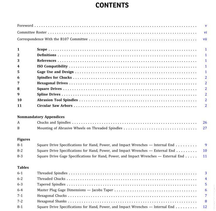
See Tables 6-1 through 6-4.
7 HEXAGONAL DRIVES
See Tables 7-1 and 7-2.
8 SQUARE DRIVES
See Figures 8-1 through 8-3 and Tables 8-1 through 8-7.
9 SPLINE DRIVES
See Tables 9-1 through 9-4.
10 ABRASION TOOL SPINDLES
See Tables 10-1 through 10-4.
11 CIRCULAR SAW ARBORS
See Table 11-1.
ASME B107.4:2019 pdf free download
