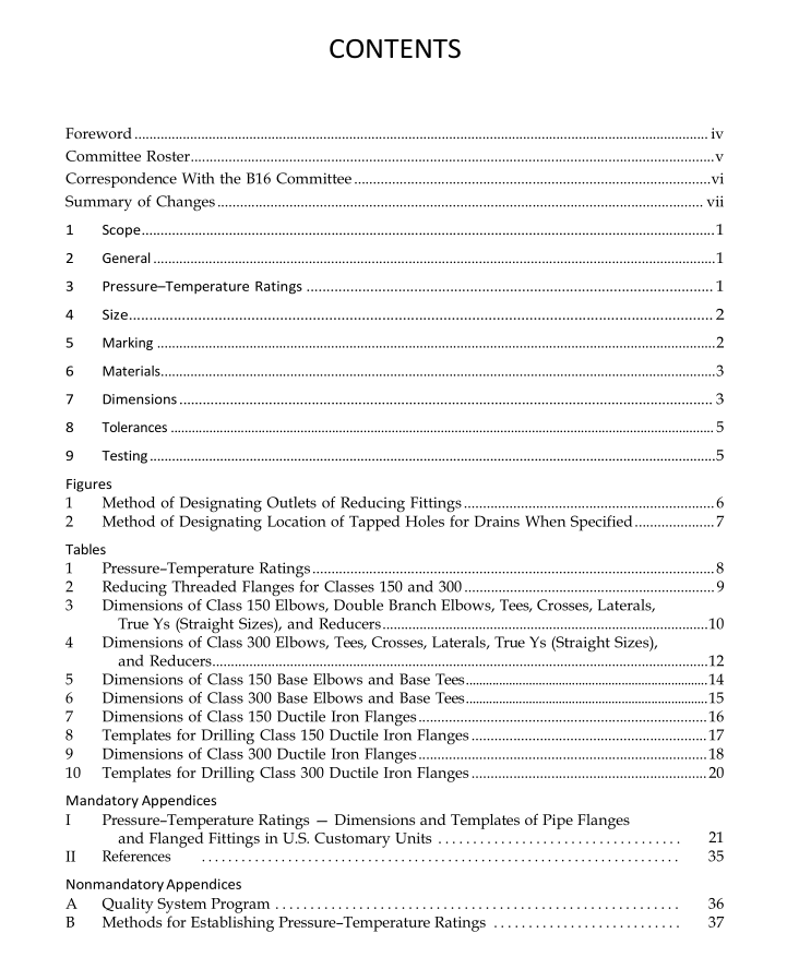
ASME B16.42:2011 pdf free download Ductile Iron Pipe Flanges and Flanged Fittings Classes 150 and 300
6 MATERIALS
6.1 Castings Ductile iron castings covered by this Standard shall conform to ASTM A395. The castings shall not be repaired by plugging, welding, brazing, or impregnation. 6.2 Bolting Bolting listed in paras. 6.2.1 and 6.2.2 is recommended to be used in flanged joints covered by this Standard. Bolting of other material may be used if permitted by the applicable code or governmental regulation.
6.2.1 High-Strength Bolting. Bolting materials hav- ing allowable stresses not less than those for ASTM A193 Grade B7 may be used with any flanged joint at all listed temperatures. The strength of the nut shall be not less than that specified for ASTM A194 Grade 2H.
6.2.2 Low-Strength Bolting. Bolting materials with yield strength equivalent to ASTM A307 Grade B are considered low strength, and may be used for flanged joints at temperatures not greater than 205°C (400°F) and only with gaskets described in para. 7.8.
6.2.3 Bolting to Cast Iron Flanges. When Class 150 ductile iron flanges are bolted to Class 125 cast iron flanges, or Class 300 ductile iron flanges are bolted to Class 250 cast iron flanges, it is recommended that low- strength boltings be used within the limitations in para. 6.2.2. If high-strength bolting is used, it is recom- mended that the mating flanges be flat faced and that full-faced gaskets (ASME B16.5, Table B-1, Gasket Group Number Ia) extending to the O.D. of the flange be used.
6.3 Gaskets Materials listed in Table B-1 of ASME B16.5 shall be used. The user is responsible for selection of gasket materials that will withstand the expected bolt load without injurious crushing and that are suitable for the service conditions. For low-strength bolting described in para. 6.2.2, only gaskets listed in Group Ia (ASME B16.5, Table B-1) shall be used.
7 DIMENSIONS
7.1 Center to Contact Surface and Center to End 7.1.1 Standard Fittings. Center-to-contact-surface dimensions are shown in Tables 3 and 4.
7.1.2 Reducing Fittings. Center-to-contact-surface or center-to-flange-edge dimensions for all openings shall be the same as those of straight size fittings of the largest opening. The contact-surface-to-contact-surface dimensions for all combinations of reducers and eccen- tric reducers shall be as listed for the larger opening.
7.1.3 Side-Outlet Fittings. Side-outlet elbows, side- outlet tees, and side-outlet crosses shall have all open- ings on intersecting centerlines, and the center-to- contact-surface dimensions of the side outlet shall be the same as for the largest opening. Long-radius elbows with side outlet shall have the side outlet on the radial centerline of the elbow, and the center-to-contact-surface dimension of the side outlet shall be the same as for the regular 90 deg elbow of the largest opening.
7.1.4 Fittings With Bases. Dimensions of bases for base elbows and base tees are shown in Tables 5 and 6.
7.1.5 Special-Degree Elbows. Special-degree elbows ranging from 1 deg to 45 deg, inclusive, shall have the same center-to-contact-surface dimensions as 45 deg elbows; those over 45 deg to 90 deg, inclusive, shall have the same center-to-contact-surface dimen- sions as 90 deg elbows. The angle designation of an elbow is its deflection from straight-line flow and is also the angle between the flange faces.
7.2 Facings
7.2.1 General. Class 150 fittings and companion flanges are regularly furnished flat or with a 1.5 mm (0.06 in.) raised face. Class 300 fittings and companion flanges are furnished with a 1.5 mm (0.06 in.) raised face. The raised face is included in the minimum flange thickness dimensions, Q, as given in the tables.
7.2.2 Facings of Blind Flanges. Blind flanges need not be faced in the center if, when this center part is raised, its diameter is at least 25.4 mm (1 in.) smaller than the inside diameter of the corresponding pressure class fittings, as given in the tables. When the center part is depressed, its diameter shall not be greater than the inside diameter of the corresponding pressure-class fittings, as given in the tables. Machining of the depressed center is not required. 7.2.3 Flange Facing Finish. Contact faces shall be finished in accordance with MSS SP-6. 7.3 Flange Bolt Holes Bolt holes are in multiples of four so that fittings may face in any quadrant. Pairs of bolt holes shall straddle the centerlines.
ASME B16.42:2011 pdf free download
